ENSC 220 – Lab 3 Report
Review of Function-Generator / Oscilloscope Operation & Op-Amp Circuits
Names / IDs / Bench
- Kian Bellinger – 301554307
- Tyler Lee – 301560642
- Kavahn Ahluwalia – 301581033
- Bench 2
Part 1 - Instrumentation
-
I feel like we don’t need to make a report for part 1 as there is not calculations or anything other than following the steps
Part 2 – Op-Amp Circuits
3.1 Component Inventory (measured with DMM)
| Nominal | Measured (kΩ) |
|---|---|
| 2 k2 | 2.177 |
| 3 k3 | 3.240 |
| 10 k | 9.867 |
All circuits powered from ±12 V (DMM: +12.015 V / –12.012 V).
3.2 Comparator #1
Circuit – Voltage divider sets a fixed reference for the non-inverting input; inverting input receives a 100 Hz 1 Vpp triangle
3.2.1 Reference voltage calculation
The divider uses the 10 kΩ (top) and 3 k3 Ω (bottom) resistors from +12 V to ground:
3.2.2 Measured values
| Parameter | Value |
|---|---|
| 3.044 V | |
| 3.20 V | |
| +11.60 V | |
| –10.80 V |

Figure x – Triangle input (yellow) & comparator output (blue) with cursor on .
Discussion – The measured reference is within ≈ 2 % of theory; the offset between +11.60/–10.80 V and ideal rails indicates the TL072’s output-swing limit when driving 5 kΩ scope load.
3.3 Comparator #2
Comparator #2 swaps the divider to the inverting input, producing an inverted logic polarity.
| Parameter | Value |
|---|---|
| Same | 2.97 V |
| 3.20 V | |
| unchanged |
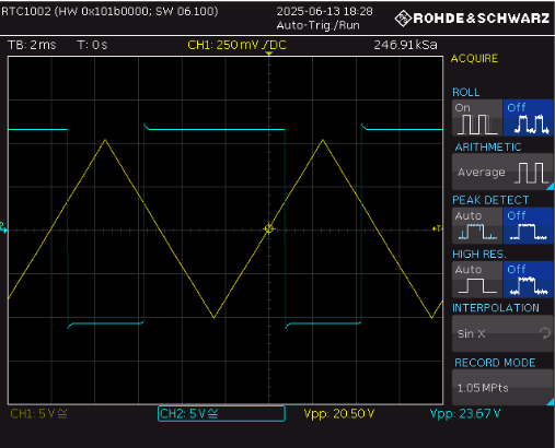
Figure 5 – Comparator #2 waveforms.
Observation – Output toggles when the input falls through (, confirming inversion.
3.4 Inverting Amplifier
Schematic parameters .
3.4.1 Gain theory
3.4.2 Measurements
| Quantity | Value |
|---|---|
| 2.07 V | |
| 6.06 V | |
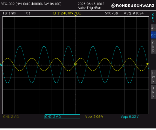
Figure 6 – Inverting amp; note phase inversion (blue vs yellow).
% error
3.5 Non-Inverting Amplifier
Schematic parameters feedback.
3.5.1 Gain theory
3.5.2 Measurements
| Quantity | Value |
|---|---|
| (V_{in(pp)}) | 2.09 V |
| (V_{out(pp)}) | 8.07 V |
| (A_{v,;scope}) | 3.86 |
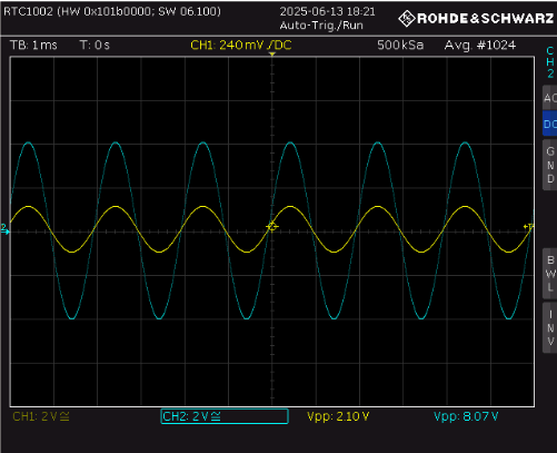
Figure 7 – Non-inverting amplifier waveform; no phase inversion.
% error